Sweeney team leaders, Dennis Weaver and Rich Deegan walk us through the planning and implementation of this open-concept kitchen remodel
The homeowners of this ranch-style home wanted to convert their home’s existing closed-off floorplan into a spacious new open kitchen, dining area and great room. Their vision for an open floor plan would require removing a wall that separated the kitchen from the dining room and living area—a wall that was load bearing. In order to remove the load bearing wall, they would need to put a header in the opening to carry the weight of the second floor and roof system.
The Challenge
The existing wall that separated the wall from the kitchen created a 10.5-foot opening. To open up the space to the full width of the room, which was 20 feet, significant support was needed to secure the load.
The Solution
We consulted with our structural engineer and fabricator in the design and estimating phase to calculate the required load bearing changes. The solution involved installing a 20’ steel I-beam in the area where the wall was removed to carry the weight, replacing the existing smaller wood support beam. At each end of the new beam the team needed to install steel support posts on both sides for it to sit on—each post to carry at least 15,000 lbs. per code. This base was secured in concrete footing in the basement to sufficiently carry the added weight.
The Detailed Planning Behind the Execution
Removing load bearing walls to achieve an open concept floor plan is a common design feature requested by many Sweeney clients. It requires significant planning, specifically how the weight supporting the second floor will be supported. With substantial experience in this, our robust team of skilled craftsmen, field project managers, engineers and designers made the process appear seamless.
The Sweeny crew, led by Dennis, planned every detail with all 9 team members weeks in advance. Before moving the beam, everyone knew exactly what was going to happen, when it was going to happen and how it was going to happen. Safety concerns were of paramount importance, along with logistics, code requirements, architectural design, man hours, muscle, costs, etc.
Part of this detailed planning process included precisely measuring where the joists were going to be placed so that the holes could be pre-drilled every 16” into the I-beam in a “W” pattern (low and high down the beam). The bolts needed to fall into open spaces that wouldn’t interfere with the joists, so bolt placement was critical. These specifics were communicated to the supplier so that the I-beam was delivered with the holes drilled to spec.
Breaking Down the Details
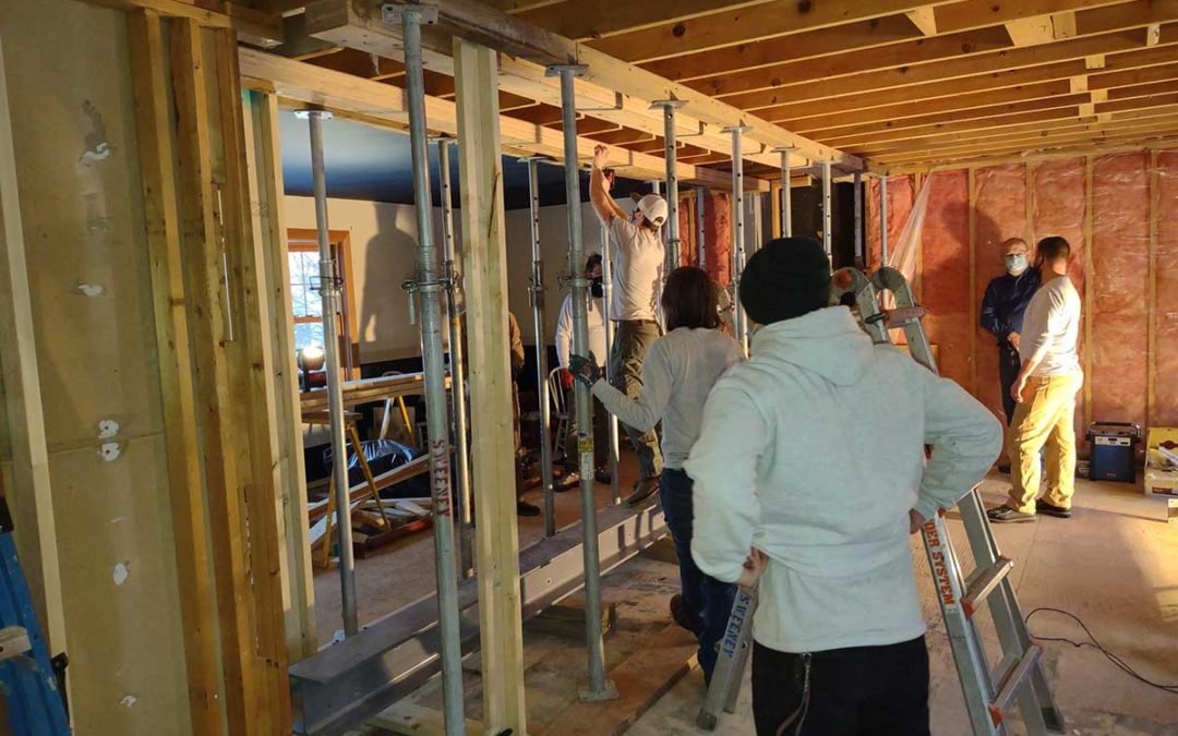
Step 1—Installing the Temporary Support Structure
Before removing the existing load bearing wall, the weight that it was carrying needed to be temporarily supported while the permanent support modifications were being installed.
Sweeney installed a temporary support structure that included metal extendable shoring posts under each joist, every 32” to carry the load of the second floor.

Step 2—Bringing the 20-Foot I-Beam Into the House

After installing the temporary support structure, Sweeney brought the new 20-foot I-beam into the home. This alone required significant planning—starting with how to get it into the house.
Not only did the Sweeney crew need to fit a 20-foot steel beam into a specific, isolated room in the house (they couldn’t use a forklift and bring it over an open roof), they also had to lift this 900-lb. beam into the home using good old-fashioned manual labor.
Nine strong crew members brought the steel beam through the front door, and maneuvered it around the support posts, and out a window in the kitchen—after building a support structure up in front of the window frame to protect it. The beam was lifted and pushed on 6×6 blocks and swung around to go through the living room, jockeying it back and forth until it was in position.
Step 3—Drilled Hole Pattern in Laminated Veneer Lumber (LVLs)

The next task at hand, after getting the steel beam in the house, was to drill the same hole pattern into the LVLs that would be placed on either side of the I-Beam. This was necessary to “pad it out” and bring the beam flush with the joist hangers to secure the joists to the I-beam.
Step 4—Gradually Lift the Beam in Place

Dennis’s careful planning, included the brilliant observation that the 900-pound I-beam would weigh an additional 300 pounds once the LVLs were permanently built into it. Consequently, Dennis planned a lifting process that would gradually elevate each side of the beam (one end at a time) four feet off the ground. Like rungs on a ladder, the team bolted and stacked board to the wall on either end of the beam, gradually supporting and lifting the 900-foot beam toward the ceiling. It wasn’t until they were within a few feet from the ceiling that they bolted the LVLs into the I-beam (adding 300 additional pounds to the weight of the beam only in the last step) and bolted it to the joists. This methodology allowed the crew to lift 900 pounds, instead of 1,200 pounds throughout the process, until the very last moment.
Step 5—Calling in the welding support
The day after the beam was set, a welder was scheduled to come in and weld the support post plate (upper and lower) to the I-beam. The screws were also welded so no one could turn them again. By welding the posts to the beam, we were able to achieve a capacity range over 16,000 lbs. We only needed 15,000 lbs.
Step 6—Structural Reinforcements in the Basement
Inspection by the Sweeney team of the original kitchen wall and structural wood beam revealed that they didn’t stack over the steel beam in the floor. It was offset over the center. As a solution, Sweeney poured a new 24” x 24” x 12” deep footing in the basement that was filled with concrete to add another steel post, which ran up to the center of the beam in the ceiling.
With the new I-beam fully supported, the Sweeney team is now ready to finish around the posts and beams, and complete any patching work along the ceiling and floor. They will be cutting and attaching pieces of drywall, then taping, mudding, and sanding the joints. They will also be replacing and repairing the ceiling and floor, as well as the trim work.
The homeowners of this 1970s home is now one step closer to getting the open floor plan of their dreams. Nice work Sweeney team!!